Technical Question on Safety Brake Adjustment
I'm having a problem.
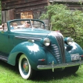
I'm trying to adjust the "safety brake", and the hardware on my '37 Terraplane does NOT match that in the manual!
Can someone help me?
Normally there is a threaded rod with a nut and lock nut, and you adjust the nuts to allow about 1-1/2" between the nut and the sliding linkage (or "control lever" as Hudson puts it). Easy to do; you just take a measurement, adjust the nut, and you're done. (See on my PDF, "the way it's sposed to be")
Mine is not like that. There is only one nut (a lock nut). The entire sliding link is threaded and rotates for adjustment. Once it's adjusted, the lock nut is tightened against the end. The problem is, it's not evident where to take the adjustment measurement! (See on my PDF, "what's actually on my car").
You rotate the "lever" (which is actually a tube) and it moves forward or back, but I can see no marking on the rear linkage rod, as to where you measure your adjustment from.
Possibly someone has transplanted a linkage from a later Hudson. (Is it like this on the StepDowns?)
If you can offer a suggestion I would be grateful!
0
Comments
-
I removed the mystery part and photographed it. Here it is:
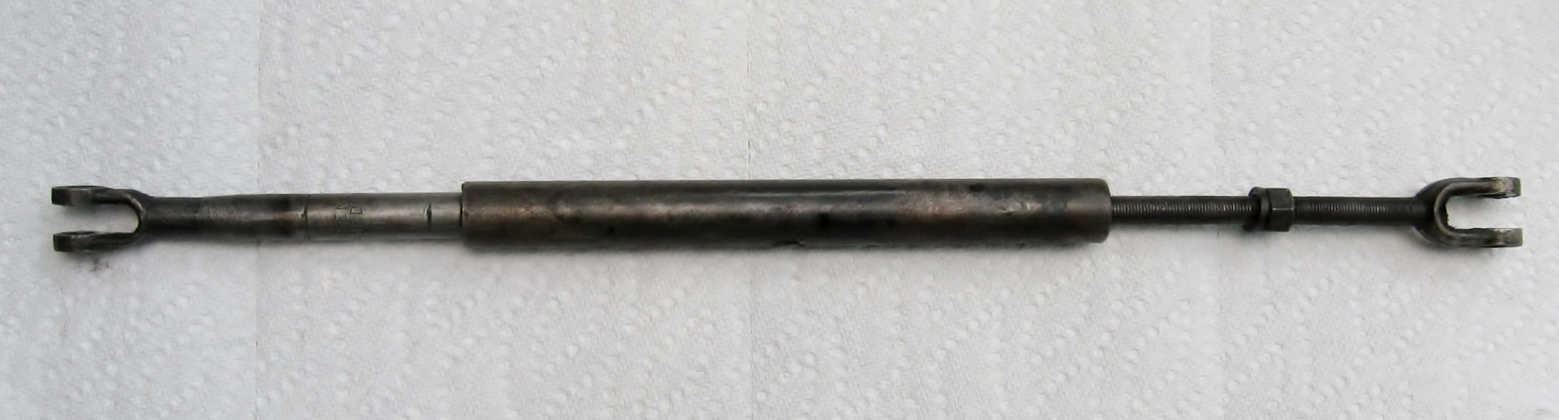
It consists of three parts:
1. The rod at left with a yoke welded on. This connects to the rear emergency brake cable linkage. The rod moves into the tube until it hits the end of the bore, then it can move no further.
2. The tube at center. The left end is bored for the rod to slide in and out. The right end is threaded internally.
3. The threaded rod at right, with its welded yoke. This connects with the brake pedal linkage. It threads into the right end of the tube, and has a lock nut on it.
When you depress the brake pedal, the threaded rod moves toward the back of the car, and the tube moves with it. Under normal circumstances, the master cylinder plunger pushes fluid through the system to all four brake cylinders, activating the brake shoes and stopping the car.
Should the fluid leak out, the brake pedal keeps moving down, pushing the threaded rod and tube along the rod at left. .The tube finally bottoms out on the left rod, and then pushes it -- which pulls on the emergency brake cables and stops the car before you hit the tree.
Just how far that tube moves, depends on where it's located on the threaded rod. That's determined by rotating the tube, which moves it up and down the threaded rod. You then then lock it in place on the threaded rod, with the lock nut.
Adjustment markings are scribed on the left rod. The left scribe mark shows the point at which the left rod will bottom out inside the tube. The right mark shows where the tube should sit under normal circumstances, in order to provide 1-1/2" of free play before the safety brake is engaged.
This is NOT the linkage that is pictured in the Hudson shop manuals for the late 1930's. That original linkage evidently consisted of the tube with a yoke welded on. There was no left rod. The threaded rod (at right) slides in and out of the tube. There were two nuts (the stop nut and the lock nut) on the threaded rod. One adjusted the nuts 1-1/2" away from the right end of the tube, so that the threaded rod slid into the tube (as you pressed on the footbrake) until the nut contacted the tube, then the threaded rod pushed the tube (and the cable linkage), engaging the emergency brakes.
Here is a closeup of the rod at left, showing the adjustment markings: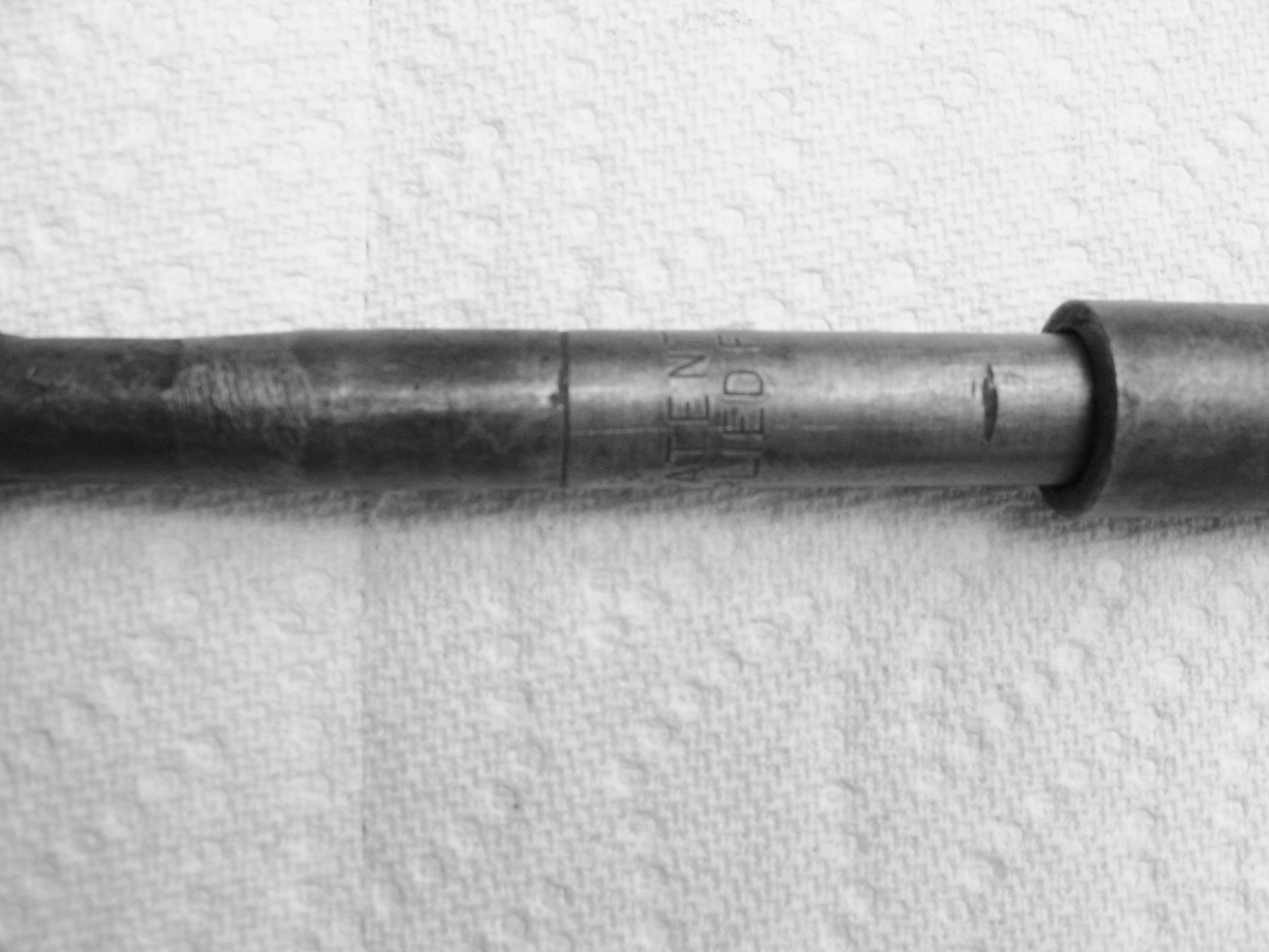
Has anyone ever seen the setup that I have pictured above? Is it a later replacement for the earlier safety brake linkage, or is it an aftermakred or home-made unit? I'd be curious to know!
0
This discussion has been closed.
Categories
- 36.6K All Categories
- 85 Hudson 1916 - 1929
- 11 Upcoming Events
- 73 Essex Super 6
- 28.4K HUDSON
- 511 "How To" - Skills, mechanical and other wise
- 990 Street Rods
- 150 American Motors
- 170 The Flathead Forum
- 47 Manuals, etc,.
- 71 Hudson 8
- 40 FORUM - Instructions and Tips on using the forum
- 2.7K CLASSIFIEDS
- 592 Vehicles
- 2.1K Parts & Pieces
- 76 Literature & Memorabilia
- Hudson 1916 - 1929 Yahoo Groups Archived Photos